Macalloy Post Tensioning System
Macalloy Bar Systems are ideal for the economic application of post-tensioning forces on relatively short tendons.
The robust coarse thread (CT) on the Macalloy bar ensures rapid and reliable assembly. This is particularly suitable for onsite use and reuse.
This listing contains the following information:
- Bar Dimensions and mass
- Mechanical properties for bars
- Characteristic loads for bars
- Component parameters
- Suggested end block reinforcement
- Minimum anchorage spacing and edge distance

Calculated Values
Loss due to concrete shrinkage
ΔPs = 1 kN
Loss due to concrete creep
ΔPc = 1 kN
Loss due to lock-off
ΔPlo = 1 kN
Loss due to friction at distance x from the anchorage
ΔPµ = 1 kN
Loss due to relaxation of steel
BS4486 specifies a maximum relaxation at 1000 hours for initial loads of 60%, 70% and 80% of the characteristic failure load. For a load of 70%, the requirement is for maximum of 3.5% relaxation. Macalloy 1030 bars perform comfortably within this requirement, with typical values less than 3%. A typical relaxation curve is shown below:
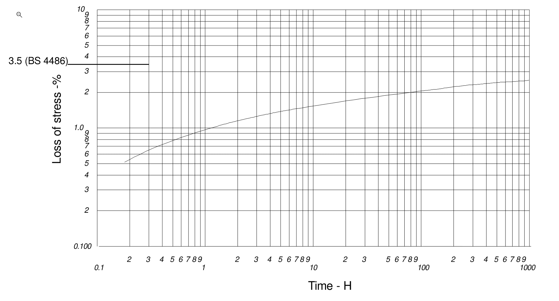
Figure:
Typical stress relaxation curve for 40mm bar at 70% UTS
Loss due to elastic deformation of the concrete
There is no loss of force in a tendon due to elastic deformation of the concrete when that particular tendon is being stressed, as the ‘shortening’ of the concrete is included in the travel of the jack ram and subsequent bar extension after lock off.
When several tendons are stressed in succession, there can be a progressive loss of prestress. This can be calculated on the basis of half the product of the modular ratio and the stress in the concrete adjacent to the tendons averaged along their length. Alternatively, the loss of prestress may be exactly computed on the basis of the sequence of tensioning. It is usually sufficiently accurate to assume that the tendons are located at their centroid.
For most applications, it is sufficient to calculate the total movement of the jack ram, ie. the sum of the theoretical bar extension and the concrete ‘shortening’, based on the full prestressing force. For multiple tendons in close proximity, this may result in a force in the bars slightly greater than the design value, when the ‘concrete shortening’ is based on full load in all tendons. However, the force in the first tendons to be stresses will falling to the design value as subsequent bars are stressed.
Loss due to concrete shrinkage
The loss of prestress in the tendon is obtained from the product of the concrete shrinkage per unit length of the concrete and the modulus of elasticity of the tendon.
The table is not uploaded or the values for the variables: Bar type do not match table records.
The table is not uploaded or the values for the variables: Environment do not match table records.
The table is not uploaded or the values for the variables: Bar type do not match table records.
Not Available
Loss due to concrete creep
The loss of prestress in the tendon as a result of concrete creep is the product of the creep per unit length of the concrete and the modulus of elasticity of the tendon. The creep per unit length, per unit applied stress, may be obtained by dividing the creep coefficient by the modulus of elasticity of the concrete at transfer.
The table is not uploaded or the values for the variables: Environment do not match table records.
The table is not uploaded or the values for the variables: Bar type do not match table records.
The table is not uploaded or the values for the variables: do not match table records.
Not Available
Loss at the anchorage on transfer of load from the jack
Any loss of stress at the anchorage during transfer of load from the jack to the nut can be attributed to several factors:
- The presence of dirt or angular misalignment between the bearing faces of the plate, washer, and nut.
- The take-up of thread tolerances between the bar thread and the nut.
- Deformation of the bearing surfaces under load.
- The bearing surfaces between the nut, washer, bearing plate, and concrete/grout are smooth, clean, and parallel.
- The applied load is cycled several times from zero to full load. This helps bed down all bearing surfaces, reducing the lock-off loss before finally releasing the jack.
The table is not uploaded or the values for the variables: do not match table records.
Not Available
Losses due to friction in the jacks
All Macalloy jacks are calibrated against a master gauge before dispatch. The loads exerted by the ram are tabulated in relation to the pressure gauge readings. This calibration process accounts for any friction in the jack, ensuring that accurate readings are obtained when using the calibration data to control the applied load.
For on-site recalibration or precise load control, electrical or mechanical load cells are available. These offer greater accuracy than standard commercial pressure gauges.
It is important to note that loads calculated from pressure gauge readings—which are based on the ram area of the jack—do not include an allowance for jack friction. Therefore, accurate calibration values should be obtained from the jack supplier.
Loss due to friction in the anchorage
There is no friction loss in single bar anchorages.
Loss due to friction due to variation in the duct profile or wobble of the duct
Friction of the bar relative to the duct due to unintentional variations in the profile or wobble of the duct relative to the bar may occur. The loss of load due to friction at distance x from the
anchorage can be calculated in accordance with Eurocode 2, EN 1992-1-1: 2004
Not Available